breadboard-io
Introduction
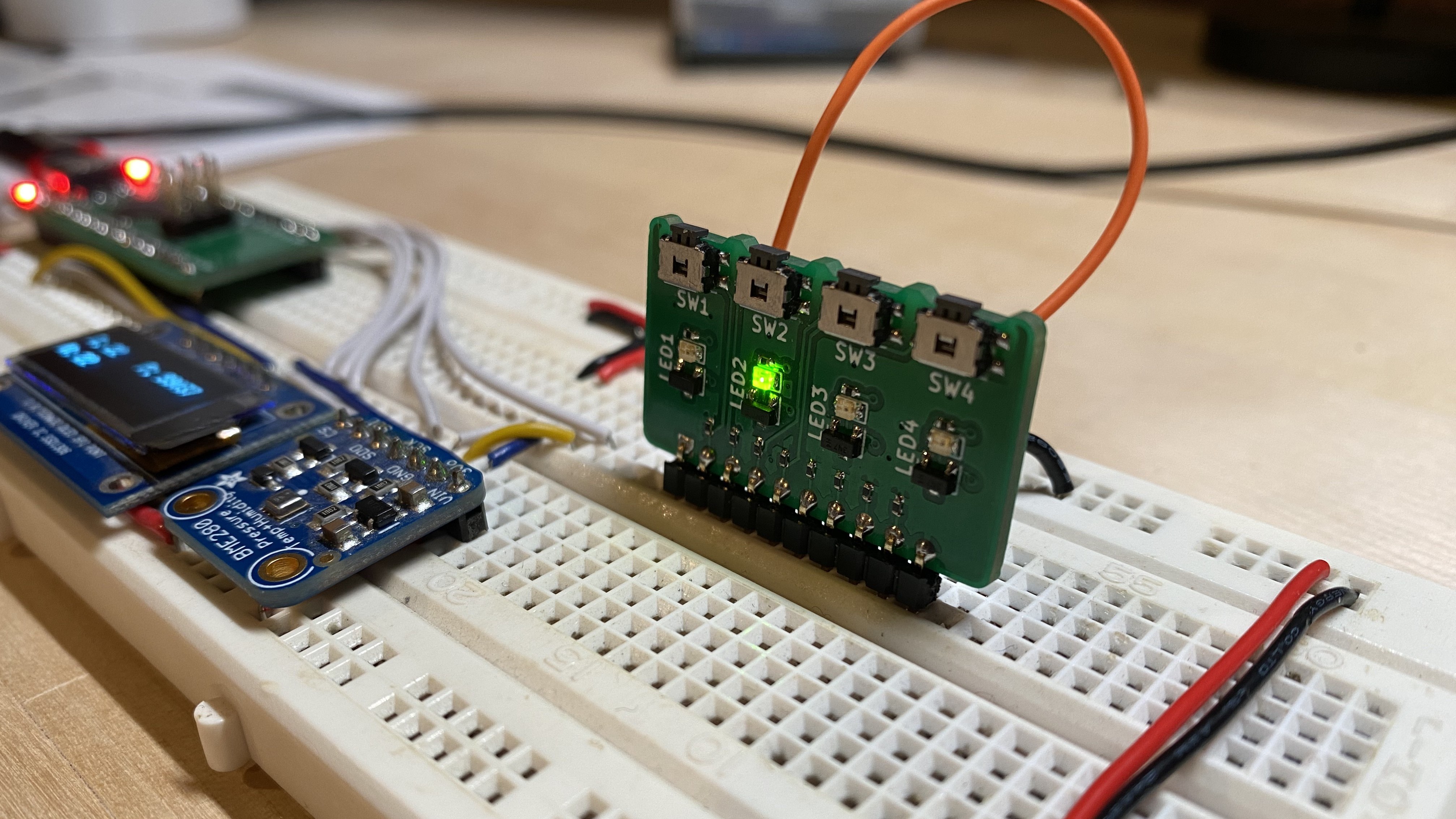
breadboard-io makes it easy to connect 4 LEDs and 4 push-buttons to a breadboard in a compact and neat footprint. Provide VCC, GND and your signal wires to other circuitry or microcontroller and you're ready to go!

If you need to debug the board, build your own PCB or just understand the design better - you can find the design files, latest release gerbers, BOM, schematic and 3d STEP model on Github.
Hardware Overview
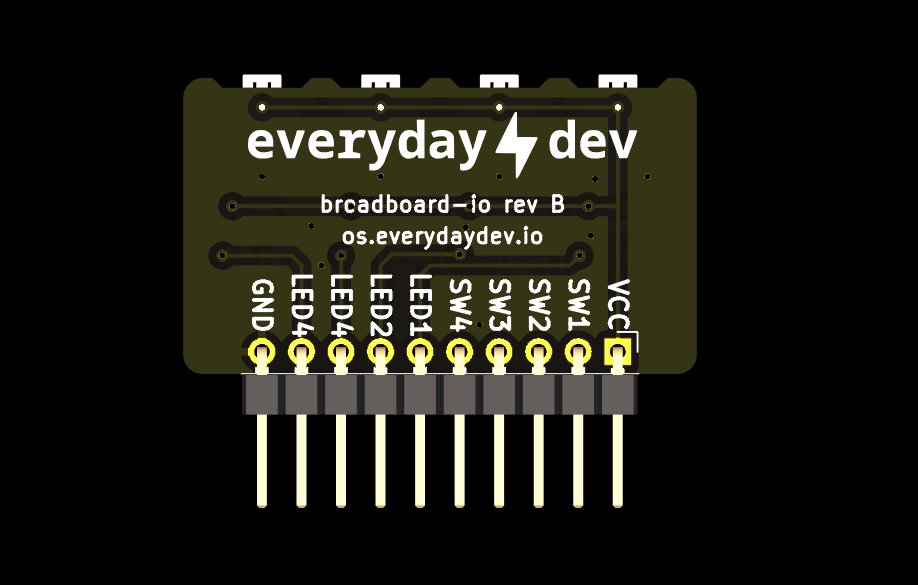
breadboard-io provides the user access to the following via a single 2.54" pitch pin header:
- 4x
Active Highpush-buttons (labeledSWx) - 4x
Active HighLEDs (labeledLEDx) - 1x
VCCpin to apply power to the board - 1x
GNDpin for grounding the board
Active High means that the "thing" will turn on, or is active, when VCC is present - aka the signal is "High". Thus Active High.
To use breadboard-io you must at a minimum provide a voltage power rail to the VCC pin, a ground connection at the GND pin and connect at least a single signal wire (LEDx or SWx).
The SWx output signals have a 10k ohm padding resistor to protect from any shorts between the VCC rail and GND. The SWx signals are fine for direct connection to a microcontroller or other high impedence circuits but should not be used to directly drive any larger loads like a DC motor as you'll have trouble getting the current needed. Instead consider using a FET to control your load and then enable the FET gate using the SWx output.